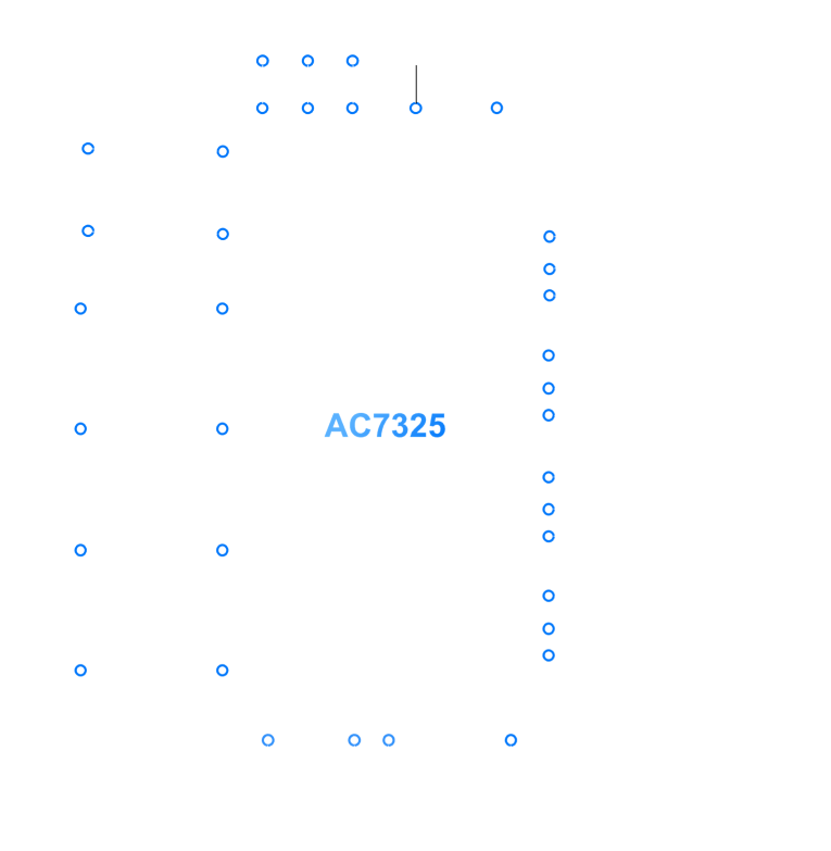
symbol
pin
description
adsel
1
i2c-busaddressselect
stby
2
standby pin
pgnd2
3
channel 2 power ground
out2
4
channel 2 negative output (left rear)
diag
5
diagnostic and clip detection output
out2
6
channel 2 positive output (left rear)
vcc1
7
power supply voltage1
out1
8
channel 1 negative output (left front)
pgnd1
9
channel 1 power ground
out1
10
channel 1 positive output (left front)
svr
11
half supply voltage filter capacitor
in1
12
channel 1 input
in2
13
channel 2 input
sgnd
14
signal ground
in4
15
channel 4 input
in3
16
channel 3 input
acgnd
17
ac ground
out3
18
channel 3 positive output (right front)
pgnd3
19
channel 3 power ground
out3
20
channel 3 negative output (right front)
vcc2
21
power supply voltage2
out4
22
channel 4 positive output (right rear)
scl
23
i2c-bus clock input
out4
24
channel 4 negative output (right rear)
pgnd4
25
channel 4 power ground
sda
26
i2c-bus data input and output
tab
27
heatsink connection;must be connected to ground


